Subject: Modeling trade-offs between light capture and electron transport on a solar cell using an interactive game
Grade Levels: Elementary school and higher
Lesson Length: 15 minutes
Authors: Brian Tracy, Tiffany Rowlands, Maxwell Cotton
Solar cells have a limited amount of space on their surfaces. The silicon wafer must be exposed to sunlight for electron/hole pair generation to occur. This is commonly the blue portion observed on the solar cell. The metal busbars/fingers (silver lines) are present to enable the transportation of current to a device. In other words the busbar/fingers are providing the “highways” to travel on and the silicon wafer represents the “electron’s home”. Maximizing the amount of current in a circuit requires tradeoffs in design between electron generation and transport. This is achieved by deciding how many and what size the busbars/fingers are as well as how much of the surface area of the silicon wafer is exposed. In this activity, participants model some of the trade-offs between the amount of busbars/fingers and the area of exposed silicon using a musical chairs-like game. This activity needs a minimum of 10 students and no maximum number is required.
Learning Goals
Participants will learn how the silicon wafer and the metal contacts differ in their effect on the solar cell’s overall efficiency and how optimization must reach a happy medium between the materials’ surface areas to maximize efficiency.
Materials
- 1 chair per student
- Masking tape
Setup
Using the tape, mark a square on the ground. Declare this the “solar cell”. The square should be small enough that students can have tradeoffs, but large enough that you can see the effect of varying the finger/ busbar spacing. Aim to just barely fit one chair for every student present.
Leave two gaps at opposite ends of the square. These are the connections to the device. The goal is to maximize how many students can pass through these points. (For more information about polarity and current flow in a solar cell, see http://pveducation.org/pvcdrom/light-generated-current)
Instructions
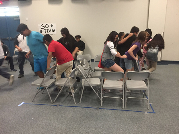
Participants will play a game with chairs to physically demonstrate electron/hole generation and transport and how the two interact with one another.
To begin, select a student to be a leader. Have all the students with their chairs stand around the square and explain the rules of the game. These rules are as follow:
- All chairs used must be completely in the square (none hanging over the lines).
- All students participating in a round must start in a chair. (Not all the chairs will fit in the optimum design, so not all students will be able to participate in each round).
- No climbing over chairs (safety first).
- Students will be given a set amount of time to move through the solar cell to make it to the device. Each student that makes it through the solar cell to the device will earn a point.
Have the student leader direct the students in placing the chairs in the square. Once the students are sitting in their chairs the teacher will indicate how much time the students have to pass through the cell, and set a timer.
Start timer, and tell the students to “GO!” and count how many students make it through to the device before time runs out.
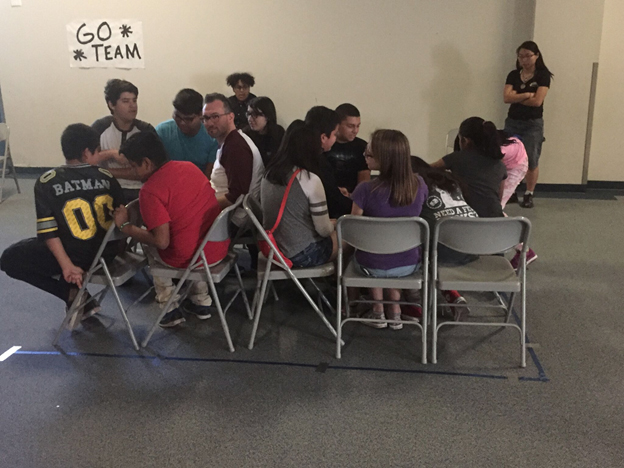
Reset the solar cell design using different chairs/aisles patterns. Use the same amount of time as before and run it again to observe any changes. Compare the pros and cons of different designs.
Helpful Hints to the Teacher
Students sitting in the chairs represent the electron/hole pairs. The students are the electrons and the chairs are the holes, generated within the silicon wafer when illuminated by a light source.
The aisles are the “highways” and represent the busbars/fingers of the solar cell. Depending on how many highways are available will determine how much current will pass through the device.
For the first run, fill the square with as many chairs as possible. This will maximize the amount of students in the round thus they potentially could get the highest score. After the run, we would expect not everyone to pass through. If everyone did, decrease your time. Ask the students,
Why didn’t everyone get out? This is because there was not enough busbar/fingers to travel on. So, we can generate all these electrons, but if we can’t get them out, what good is it?
For the second run, do another extreme and have almost no chairs. Everyone will pass through. However now we didn’t have enough electrons to produce current.
For the third run, find a happy medium where students can get enough chairs and still be able to pass through the solar cell.
Deepen your Knowledge
In solar cells the top surface is one polarity (+ or -) and the bottom surface is another. These surfaces must be connected to make your positive and negative terminals. However, the number of connections can be varied. One way to demonstrate this is to change the number of gaps in the solar cell set up. What effect would multiple gaps have on the device performance? Solar cells are not all the same. In practice, some have 2 busbars, some have 3. What are the advantages/disadvantages to having 2 or 3 busbars?
Busbars are the large thick contacts, fingers are the small (sometimes hard to see) lines. Did you see any effect of varying your busbar/fingers thickness?
What is the difference between a semiconductor, insulator, and metal? Diagram where they are located on your solar cell.
- Semiconductors when carefully put together can make interesting devices. The silicon wafer is the semiconductor in the solar cell (blue part).
- The busbars/fingers are the metal in the solar cell. Metals are good conductors.
- The lamination that encloses the solar cell to protect it is an insulator. Insulators prevent current flow insuring your electrons flow where you want them to.
For more information on how a solar cell is made, see activity “Solar Cell Assembly Line”
Follow up this activity with the front grid optimization activity in the Classroom Lessons section.